panhard
Ma Panhard 24CT
 1 Panhard and owner - photo gus robinson |
 2 and again. Note original garage folding doors |
 3 and yet again |
 4 When it was delivered to us. Old rego plates |
 5 In the garage now with overhead roller door |
 6 Bonnet with compressor |
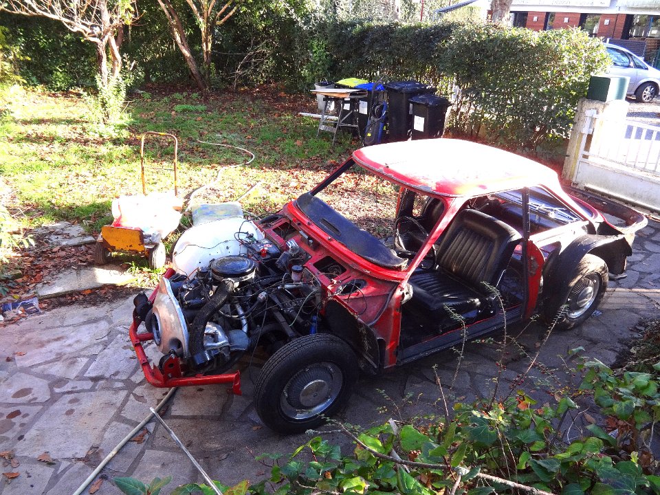
 7 They are contemporaries - 1963 |
 8 The front of the car as I first dissasembled it |
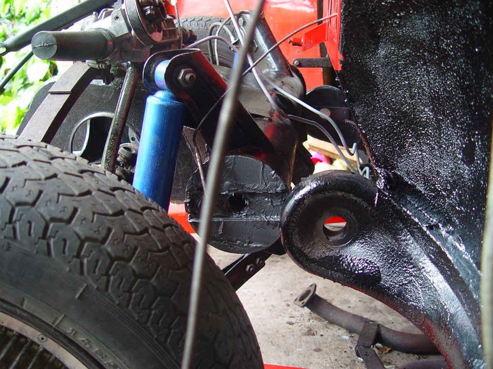
 9 The engine and gearbox removed, then the springs |
 10 The front drive train showing the tube which bolts to the front tube of the body. It also supports directly the shocks. The gearbox is ahead of the tube hidden in a welded box which supports the cradle holding the engine |
 11 A view through the opening between the rear seat and the boot. The fuel tank drops in there. The exhaust (since renewed) has an in line resonance chamber, a low impedance pipe and then a transverse silencer with twin outlets all to optimise the gas flow. |
 12 The distributor, driven by a vertical shaft from the oil pump that has a slotted hollow section which behaves as a vacuum pump. It feeds the gearbox to maintain a low pressure and retain the oil. |
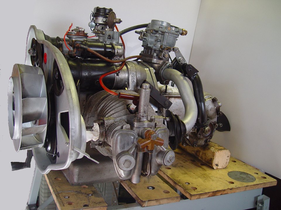
 13 The carburettor is warmed by exhaust pipe heat. As it is fed by pipes from both exhausts, there would not be much tranverse warm air flow unless it was forced from one to the other. This deflector gasket creates the asymmetry needed. |
 14 Engine during reassembly with new pistons etc. Note chevron timing gears and valve torsion bar covers |
 15 The valves showing the alignment between copper shims and the hydraulic tappets |
 16 |
 17 The low pressure oil feed to the tappets and the non return valves using brass clips in the oilways |
 18 another view of the engine assembly with temporary exhausts for bench testing |
 19 Centre of the timing gear showing the piston that actuates the oil pressure switch in the timing cover |
 20 The timing gear |
 21 The timing cover showing the pressure switch and the slipping clutch for the cooling fan |
 22 The narrow omega profiles for stiffening the floor |
 23 At the driver's feet, floor removed |
 24 Crude extra plate welded in by old repairer - under the rear seat |
 25 below the passenger's feet - floor removed |
 26 Through the car from passenger side |
 27 The garage floor below the car before floor repainting |
 28 Tentative assembly of the floor to check dimensions, big hole for gear selector, little ones for drain plugs |
 29 The floor panel in 1mm steel, electro zinc |
 30 Floor on bench ready for welding |
 31 Almost finished floor hidden from roving metal collectors |
 32 Engine removed, the lifting begins- Noël studies the limit of the crane- note the problem of clearing the folding door. The brake drum and wheel system is clearly visible |
 33 Michel studying the crane from the other side |
 34 and Noël risks a car on his foot for a closer look |
 35 view from boot, car supported on wooden planks and blocks |
 36 The front train, engine view. Note that the engine is supported by its exhaust pipes - unique? |
 37 The second crane is installed on the other side and Michel prepares for the final lift |
 38 Nearly vertical |
 39 Now vertical and Michel is setting up the wooden blocks |
 40 Vertical seen from under the engine bulhead |
 41 The rear suspension |
 42 Bringing in the motor |
 43 Rear frame corner gusset passenger side. No jacking point and crude add on for seat belt and the ledge for welding on the floor |
 44 opposite gusset driver's side being removed |
 45 Passenger side rear lower flange removed |
 46 driver side rear flange removed |
 47 rear floor mount cleaned for rust treatment |
 48 First fit of floor - perfect |
 49 Driver side front flange before removal |
 50 Passenger side front flange before removal |
 51 Front suspension -work of art |
 52 front suspension showing joint on the tubular chassis member, steering rack and stub axles. Note fabricated lower arms |
 53 more suspension |
 54 The stub axle |
 55 axle assembled |
 56 suspension reassembled note handbrake cable and drive shaft damper |
 57 ready to accept the front drive train |
 58 front train less engine and gearbox , note alloy finned drums |
 59 a crane is invaluable - 2 tonnes max. |
 60 The ends of the tube greased for reassembly. |
 61 ready to slide into the tubular frame chassis |
 62 On its way |
 63 Almost in place |
 64 getting closer |
 65 |
 66 fitted |
 67 bolted in place |
 68 With a hollow bolt each side |
 69 engine and gearbox slide into the box. |
 70 In place - note fan, generator and starter |
 71 The gear selector turret waiting to be fixed and adjusted. the black exhaust pipes heat the block under the carby. |
 72 On the bench - note the oil distribution to the tappets |
 73 The front of the gearbox and clutch housing |
 74 The speedo take-off |
 75 speedo take-off pinion and the selector rods exposed |
 76 The selector rods |
 77 Cover of the intermediate drive shaft, coupling to drive shafts below |
 78 removing the output flanges |
 79 Turns the wrong way on that side! |
 80 |
 81 The diff behind the intermediate drive pinion, note roller bearing. |
 82 The output shaft housing cover - note the needle and roller bearings- money no object |
 83 other side |
 84 unscrews normally |
 85 Cover showing yet another needl roller bearing |
 86 This side -another roller race |
 87 Adjustment screw on side of box which limits 4th gear selector movement to facilitate assembly |
 88 unscrewed to release the selector |
 89 The intermediate shaft, note chevron gears |
 90 The output shaft, hollow and lubricated from the hypoid pinion end |
 91 The input shaft colinear with the output - locked to provide a direct drive in 3rd. |
 92 The final drive configuration. The central spiral drives the speeedo cable and also pumps the oil back down the hollow pinion and shaft to the gears |
 93 Front bearings - main ball race (removed by heating the alu casting) and secondary shaft - needles |
 94 |
 95 The diff |
 96 The diff |
 97 Intermediate output shaft with crown wheel, speedo gear and oil pump and drive pinion to the diff. |
 98 The finned alu drum |
 99 and its fixings |
 100 The front brake shoes. The drums have a steel lining |
 101 Boot repairs |
 102 Roof to be repaired |
 103 Boot perimeter recreated |
 104 The sand blaster |
 105 Floor in place, welding started |
 106 Welded in place with gussets |
 107 The floor inside welded in place |
 108 The floor protected with Restom Epoxy Paint and Sound deadening. Longitudinals filled with Restom protective wax. |
 109 The parcel shelf with epoxy primer |
 110 The floor inside with restom epoxy Primer and Sikaflex e-cure sealant |
 111 Modied delivery system for anti-rust wax in closed sections |
 112 Restom 4010, compressed air gun and extended delivery tube. |
 113 A happy Michel after the body was turned around. |
 114 Front of body awaiting drive train |
 115 Drive train waiting in front garden |
 116 Installed |
 117 Better view of the installation with Simone |
 118 The tank with zinc alu paint to help theoriginal electro-zinc |
 119 The other view of the tank with GS behind |
 120 Front view, waiting for fuel and ignition |
 121 Driver's seat temporarily in place |
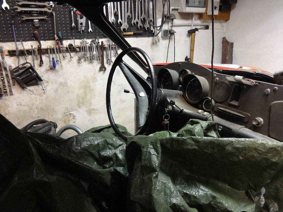
 122 The welding shop in the boot - waziting for a bottle of gas |
 123 Temporary set up of the dash |
 124 The tank Restom expoxy painted |
 125 The tank in place |
 126 With a layer of felt it forms part of the boot floor |
 127 electrics in place, ready to start |
 128 turned around under her own power 7dec 2014 |
 129 |
 130 Driven up on ramps |
 131 The carby was flooding, needle valve came loose!??? |
 132 There was once a prisoner nut there |
 133 |
 134 rust on the bracket holding the passenger door seal. |
 135 Vestige of the old floor |
 136 epoxy primer to protect the roof behind the chrome trim |
 137 Left over primer to add a layer in a closed box inside the front wing |
 138 Michel removes rotted rubber door trim |
 139 Crack in the steering wheel |
 140 Yes, the front wings fit. |
 141 and at the front |
 142 My favourite epoxy primer |
 143 The dashboard will get cleaned real soon |
 144 but first the windscreen has to go in |
 145 and its identical twin, the rear window. |
 146 Alain retouches the rear panel with epoxy primer. This panel had its lower half rotted through and was rebuilt with a right angle strip grafted in. |
 147 Captive nut - Panhard style. Weld the tabs to the panel and don't forget to put the nut inside. |
 148 The windscreen in place |
 149 The boot ready for lining with felt. |
 150 The front wings are on but the lamp connections are diabolical. |
 151 The back end is pretty tidy, new boot seal and remanufactured rear panel |
 152 Simone installs the passenger seat to cut the carpet around |
 153 Underfelt in place. |
 154 Ready, but not quite for the Contrôle technique 16 Jan 2015 |
 155 |
 156 The N-S cable across diagonal and the E-W bottom right |
 157 The E-W cable, outer right and inner left near reversing switch. Domainant black tube carries low pressure to gearbox for oil retention. |
 158 The reversing switch. LH cable is the hand brake |
 159 Twin choke carby centrally mounted on inlet pipes, neatly restricting access to the gearbox |
 160 as at 4th Feb 2015. out for a road test |
 161 not all the trim is on until the respray |
 162 GS in background |